
What is an SCR Controller?
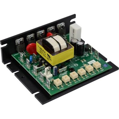
The LGC400-10 is a SCR-based DC motor control
First, What Is A Diode?
A diode is an electrical component that allows electricity to flow in one direction, but not in the other. It’s similar to a check valve that lets water flow out, but not back in. It’s also like a flap on an exhaust vent. If air is flowing in the right direction, the force of the air opens the vent and allows the fumes to escape. Once the air stops blowing, gravity closes the flap to prevent the outside air, debris, fumes, or animals from getting back in.
In the illustration below, when the incoming AC wave is positive current is flowing from left to right so the diode allows the current to flow through. When the AC wave is negative, current wants to flow from right to left, so the diode blocks it.
A diode only allows current to flow in one direction
Diode Bridges
If only one diode is used (as shown above) with an AC input, the output is known as half-wave AC because only the positive half of the AC line comes through. So how do we take advantage of the AC line when it’s in the negative portion of its phase? With a diode bridge. If you take 4 diodes and arrange them in a diamond pattern as show in the illustration below, the output of the diode bridge is always positive regardless of the AC input being positive or negative. This output is known as rectified AC.
Illustration of a Diode Bridge to convert AC into Rectified AC
Rectifier Bridge and SCRs
In the United States, the 115V and 230V AC line power sources are at 60 Hz. This means there are 60 complete waves in 1 second. For a rectified AC output then, there are 120 pulses per second. This is so fast that the DC motor acts as thought it's being powered by DC.
So now we know how we get rectified AC voltage and that it can make a DC motor spin, but how can we vary the speed of a DC motor? By varying the voltage across the motor using Silicon-controlled Rectifiers (SCRs). A SCR is like a diode, but with the added ability to be able to turn it on and off, so that the electricity not only flows in one direction, but only flows in that direction when you want there to be a flow. By replacing two of the diodes with SCRs, we convert out diode bridge into a rectifier bridge and we can control the average amount of voltage across the DC motor.
Using SCRs in place of the two incoming diodes converts a Diode Bridge into a Rectifier Bridge
One noticable difference between the outputs of the diode bridge and the rectifier bridge is that the SCR output has a delay at the start of each pulse. This is built by design into SCR motor controls to prevent the two SCRs from turning on at the same time. If both SCRs were to be on, it would create a short circuit across the AC line, which would blow breakers and/or fuses, as well as possibly damage the SCRs. This is why with a 115 VAC line source, the most amount of voltage you'll be able to get out of a SCR control is 100 VDC, which is why DC brushed motors are typically rated for 90 VDC. With a 230 VAC line source, typical DC brushed motors are rated for 180 VDC.
Variable Speed
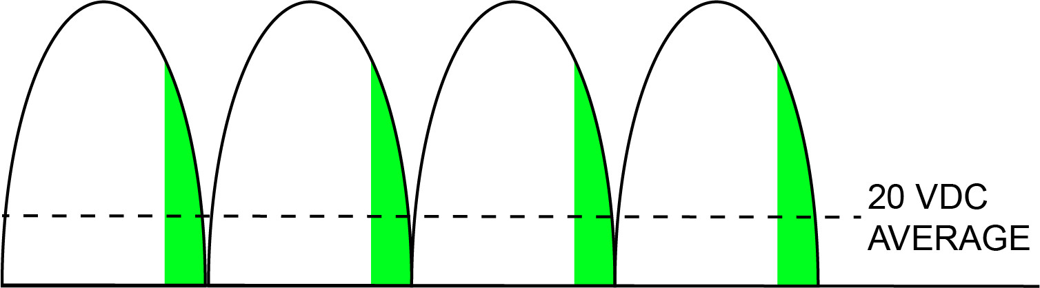
By adding a delay before turning on the SCR, we can not limit the amount of voltage allowed out across the motor. This delay is called the phase-angle. The higher the phase angle, the sooner the SCR will turn on and the longer the rectified output will be allowed across the motor. The illustration below shows a rectifier bridge with a small phase angle applied to the SCRs to run the DC motor at a lower speed. SCRs motor controls for brushed DC motors typically have a 1.37 form factor with a 60:1 speed range for a 1% load regulation. This means you can expect to turn a typical 90V DC motor down to 1.5 VDC and maintain a 1% variation (0.9 VDC in this example). Typically the lowest speed possible in any SCR and DC motor combination is determined by the motor. DC motors typically begin cogging before the drive's output becomes an issue.
Illustration of SCRs being used to limit the amount of voltage out across a DC motor
 |
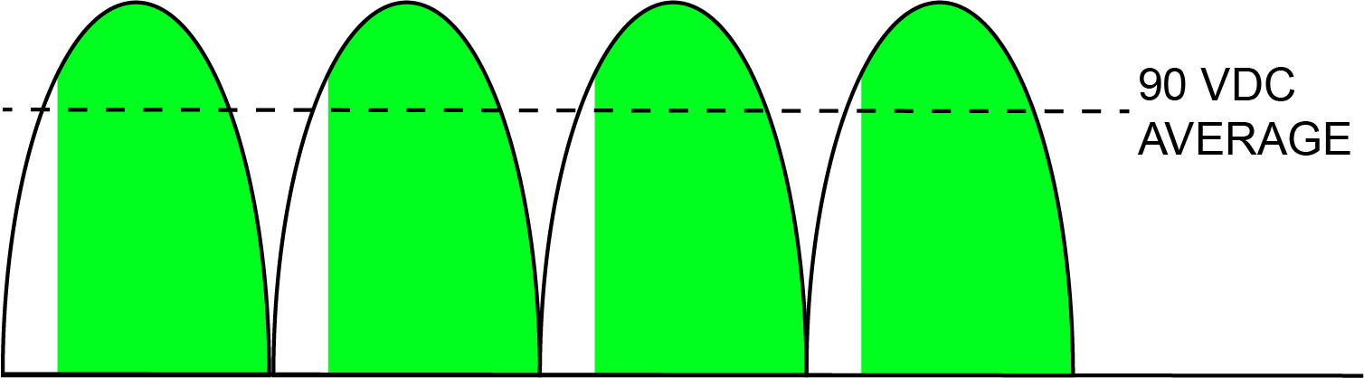 |
| SCR Output at 20 VDC (chart read left to right) | SCR Output at 90 VDC (chart read left to right) |